Interface and Application Programming
individual assignment:
write an application that interfaces a user with an input &/or output device that you made
For this week, I did our experiment with an LED using the Arduino and controlled it through a graphical interface that I created.
Things I used in my first experience
- Arduino
- Breadboard
- Couple of jumpers/single stranded wires
- 5 LEDs
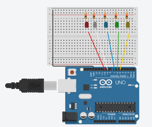
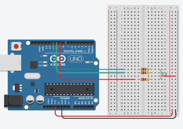
In my first experience, I connected five LEDs and controlled them through lighting and turning them off through a graphical user interface. I started connecting my circuit as shown in the image below
Then I wrote the code for my board
Arduino Code :)
    void setup() {

  pinMode(10, OUTPUT);   //set pin as output , Red led
  pinMode(9, OUTPUT);   //set pin as output , White led
  pinMode(7, OUTPUT);   //set pin as output , Blue led
  pinMode(6, OUTPUT);  //set pin as output , Green led
  pinMode(5, OUTPUT); // set pin as output , yellow led

  Serial.begin(9600);    //start serial communication @9600 bps
  }

void loop(){

  if(Serial.available()){  //id data is available to read

    char val = Serial.read();

    if(val == 'r'){       //if r received
      digitalWrite(10, HIGH); //turn on red led
      }
    if(val == 'b'){       //if b received
      digitalWrite(9 , HIGH); //turn on blue led
      }
    if(val == 'w'){       //if y received
      digitalWrite(7 , HIGH); //turn on white led
      }
      if(val == 'g') {
        digitalWrite(6 , HIGH); // turn on green led
      }
      if(val == 'y'){
        digitalWrite(5, HIGH); // turn on yellow led
      }
    if(val == 'f'){       //if f received
      digitalWrite(10, LOW); //turn off all led
      digitalWrite(9, LOW);
      digitalWrite(7, LOW);
      digitalWrite(6, LOW);
      digitalWrite(5, LOW);

      }
    }
  }
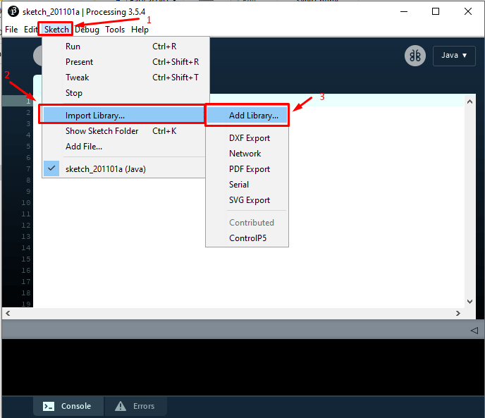
After writing the code you install processing porogram, you can create a GUI (graphical user interface) with which you can do many things. One of these things is to control and interact with an Arduino.
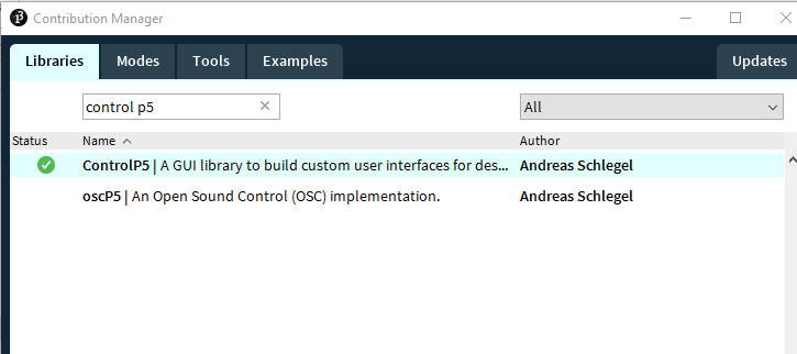
Beginning after installing the program, you install the (Control P5) library.
I start writing code to create the software interface that I use in my experiment
 background(138,151,71); //background color of window (r,g,b)

     fill (0,0,0);  // text(Title of the control page that you will create ) color

  text("LED CONTROL", 160 , 30); // give title to my window , position to the title
fill (0,0,0); // text(Title of the control page that you will create ) color
text("LED CONTROL", 160 , 30); // give title to my window , position to the title
press on Run to see how its look like.
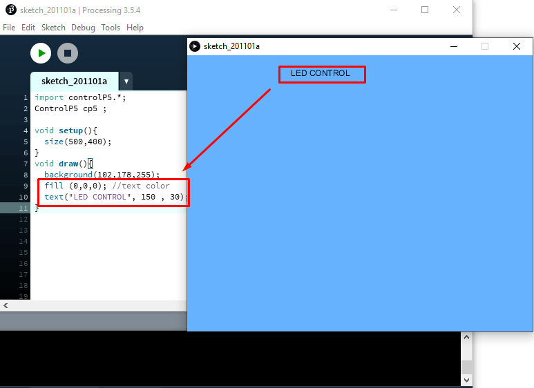
As shown in the picture this code is inside the red box to create a button to control the Led light
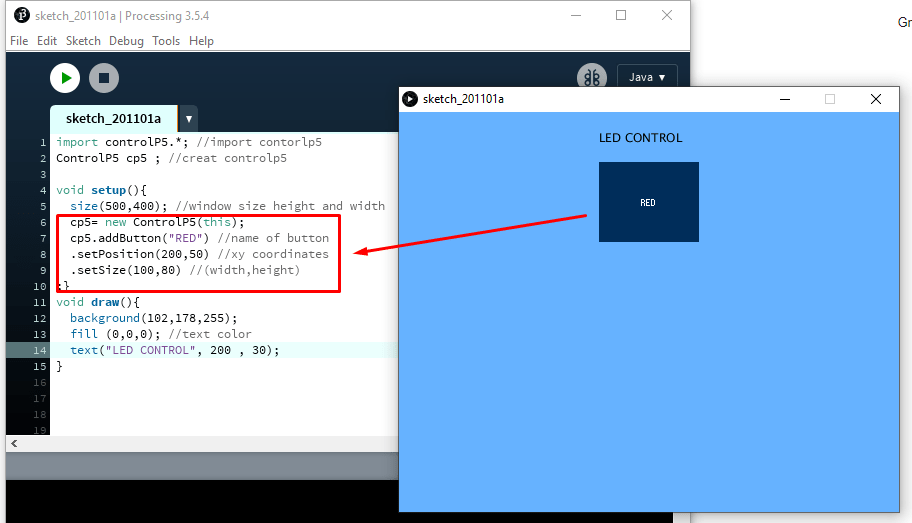
This is how window looks like:
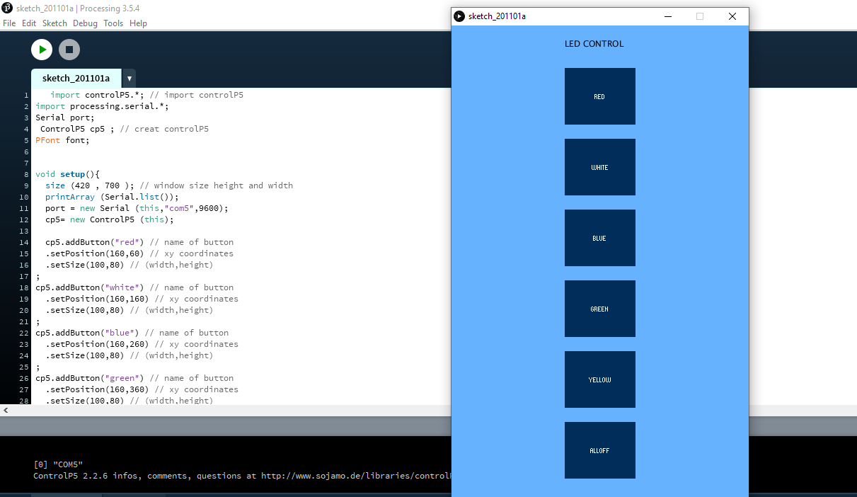
Processing code :)
    import controlP5.*; // import controlP5
import processing.serial.*;
Serial port;
 ControlP5 cp5 ; // creat controlP5
PFont font;


void setup(){
  size (420 , 700 ); // window size height and width
  printArray (Serial.list());
  port = new Serial (this,"com5",9600);
  cp5= new ControlP5 (this);

  cp5.addButton("red") // name of button
  .setPosition(160,60) // xy coordinates
  .setSize(100,80) // (width,height)
;
cp5.addButton("white") // name of button
  .setPosition(160,160) // xy coordinates
  .setSize(100,80) // (width,height)
;
cp5.addButton("blue") // name of button
  .setPosition(160,260) // xy coordinates
  .setSize(100,80) // (width,height)
;
cp5.addButton("green") // name of button
  .setPosition(160,360) // xy coordinates
  .setSize(100,80) // (width,height)
;
cp5.addButton("yellow") // name of button
  .setPosition(160,460) // xy coordinates
  .setSize(100,80) // (width,height)
;
 cp5.addButton("alloff") // all led will be on
  .setPosition(160,560) // xy coordinates
  .setSize(100,80); // (width,height)

}
void draw(){
  background(102,178,255); //background color of window (r,g,b)
  fill (0,0,0);  // text color
  text("LED CONTROL", 160 , 30); // give title to my window , position to the title

}
void red(){
  port.write ('r');
}

  void white(){
    port.write('w');
  }
   void blue(){
     port.write('b');
   }
   void green(){
     port.write('g');
   }
     void yellow(){
       port.write ('y');}
        void alloff(){
         port.write('f');}
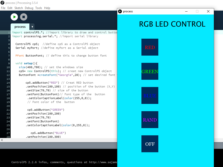
In the second experiment
I controlled the RGB LED by means of the program that prepared it specially for this experiment and through it I could control the LED to light up either (green, blue, red, , Rand or off)
The components I used
- RGB LED
- Arduino
- Three resistors
- Brerboard
- connecting wires
And the connections are as shown below

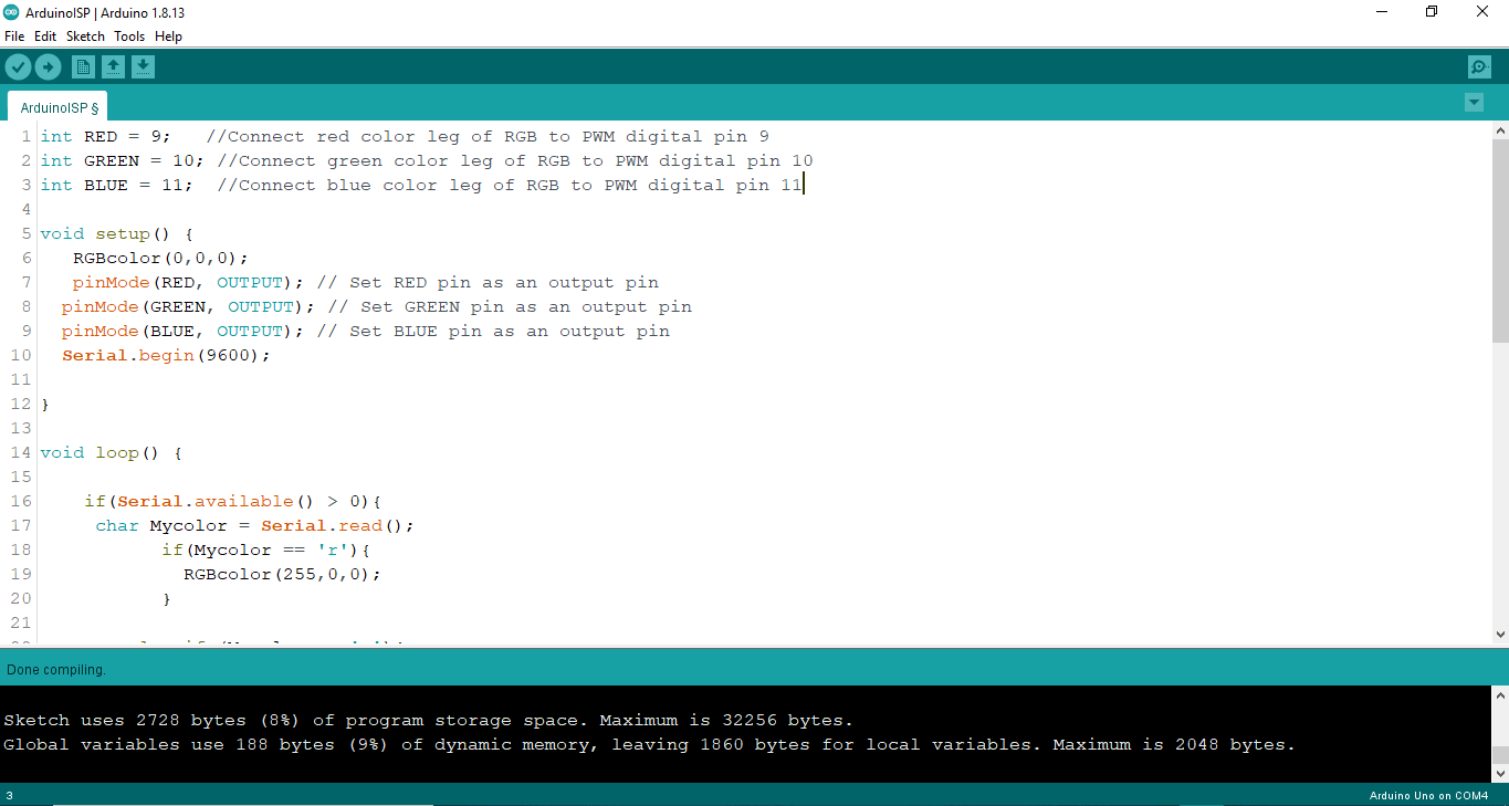
Arduino Code :)
   int RED = 9;   //Connect red color leg of RGB to PWM digital pin 9
int GREEN = 10; //Connect green color leg of RGB to PWM digital pin 10
int BLUE = 11;  //Connect blue color leg of RGB to PWM digital pin 11

void setup() {
   RGBcolor(0,0,0);
   pinMode(RED, OUTPUT); // Set RED pin as an output pin
  pinMode(GREEN, OUTPUT); // Set GREEN pin as an output pin
  pinMode(BLUE, OUTPUT); // Set BLUE pin as an output pin
  Serial.begin(9600);

}

void loop() {

    if(Serial.available() > 0){
     char Mycolor = Serial.read();
           if(Mycolor == 'r'){
             RGBcolor(255,0,0);
           }

        else if (Mycolor == 'g'){
           RGBcolor(0,255,0);
        }
         else if (Mycolor == 'b'){
           RGBcolor(0,0,255);
        }

          else if (Mycolor == 'd'){
          RGBcolor((RED,random(0,255)),(GREEN , random(0,255)),(BLUE, random(0,255)));

        }

         else {
          RGBcolor(0,0,0);

         }
      }

}

void RGBcolor(int Rval, int Gval, int Bval){

  Rval = 255-Rval;
  Gval = 255-Gval;
  Bval = 255-Bval;
  analogWrite(RED,Rval);
  analogWrite(GREEN,Gval);
  analogWrite(BLUE,Bval);

}
Processing code:)
   import controlP5.*; //import library to draw and control buttons
import processing.serial.*; //import serial library

  ControlP5 cp5;  //define cp5 as a ControlP5 object
  Serial myPort; //define myPort as a Serial object

  PFont ButtonFont; // define this to change button font

  void setup(){
    size(400,700); // set the windows size
    cp5= new ControlP5(this); // creat new ControlP5 object
    ButtonFont =createFont("Georgia",20); // set desired font type

        cp5.addButton("RED") // Creat RED button
        .setPosition(100,100) // position of the button (X,Y)
        .setSize(70,70) // size of the button
        .setFont(ButtonFont)// Font type of the  button
         .setColorCaptionLabel(color(255,0,0));
         // Font color of the  button

         cp5.addButton("GREEN")
        .setPosition(100,200)
        .setSize(70,70)
        .setFont(ButtonFont)
        .setColorCaptionLabel(color(0,255,0));

           cp5.addButton("BLUE")
        .setPosition(100,300)
        .setSize(70,70)
        .setFont(ButtonFont)
        .setColorCaptionLabel(color(0,0,255));

          cp5.addButton("RAND")
        .setPosition(100,400)
        .setSize(70,70)
        .setFont(ButtonFont)
        .setColorCaptionLabel(color(205,0,255));

         cp5.addButton("OFF")
        .setPosition(100,500)
        .setSize(70,70)
        .setFont(ButtonFont);
    myPort = new Serial(this, "COM5",9600); //connect myPort with COM3 where arduino
                                           // is actually connected ^_^
  }

  void draw(){
    background(5,233,255); // background color of the screen
    fill(0); // Text color
    textSize(30); // text size
    text("RGB LED CONTROL", 90,50); // To write the title, the position of the title
  }

  void RED(){
    myPort.write('r'); // When Button RED is pressed send 'r' to serial port
                      // in Arduino code when recive 'r' the RED color will light
  }
    void GREEN(){
    myPort.write('g');
  }
     void BLUE(){
    myPort.write('b');
  }
       void RAND(){
    myPort.write('d');
  }
         void OFF(){  // When Button OFF is pressed send 'o' to serial port
       myPort.write('o');// in Arduino code when recive 'o' RGB will  OFF

  }
For download code for The first experiment check rgb led interface .rar here
For download code for The second experience check here